Project 1 : Revit modeling and documentation
This project involves the production of Revit model of the selected architecture design using Architectural Components such as Wall, Roof, Stairs, Floor, Curtain Wall, Doors and Windows. At the end of the project, the model shall be used to generate documentation drawings, using Revit Architecture’s Documentation Components such as Sheets, Titleblock, Sections, Room Tags, Schedule & etc.
Revit modeling
Modeling process

Step 1 : Creating cad drawings of the retreat house in Auto Cad and import into revit
Step 2 : Creating floor level for the cad plan drawings and built by extrusion components and generic components.

Step 3 : Modifying the stairs railing by using modify floors with different points.


Step 4 : By creating and extruding more components and details.

Step 5 : Modifying the curve roof with modify sub elements with different points.


Step 6 : Adding material layers into the model building

Step 7 : Modifying wall into curtain wall

Step 8 : Load the door family that has been created in new family file

Step 9 : Annotate details and tags in the floor plans

Step 10 : Using detail lines to create topography

Step 11 : Adding points to the topography to follow the slope of the house

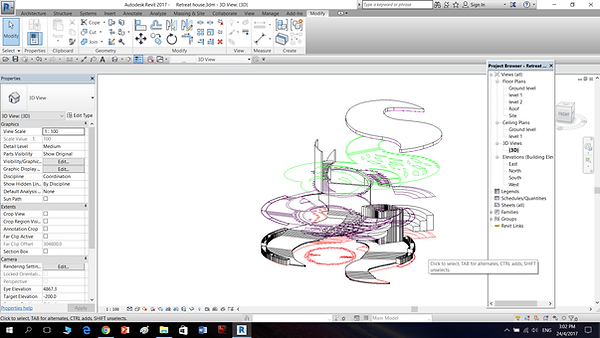
Step 12 : Creating exploded isometric and edit its features


The final outcome of the 3d model and exploded isometric
Revit family progress
Double door


Step 1 : By creating a new door family template and setting its width and height parameter


Step 2 : Creating various reference plane for frame width and thickness etc


Step 3 : After drawing on the parameter with lines, locking is a must for every line drawn.


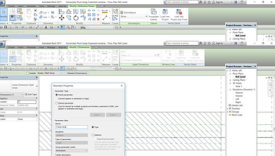
Step 4 : By creating parameter into the properties table and creating surface by extrusion.


Step 5: By using detail lines to sketch the door symbol with parameters.


Step 6 : Creating more parameter and testing. The final step is to assign materials to the double door.
Single door


Step 1 : By creating a new family door and using reference plane to draw out the door frame thickness etc.


Step 2 : By drawing lines onto the reference plane and making it align with the parameters.


Step 3 : By editing on the exterior and also creating sweep details on the reference plane.


Step 4 : By creating more door details on the plan and exterior elevation.


Step 5 : By calculating and drawing door open symbol on plan and change its visibility setting. Lastly is to assign materials to the door.
Window


Step 1 : Creating a new family window file, draw various reference plane and indicate the dimension of the height and width of the window.


Step 2 : Creating more reference plane and to create extrusion.


Step 3 : Creating parameter family and test it out, lock onto the lines when completing a drawing.


Step 4 : Final checking for the parameters and also assign materials into the project.
Annotation and Documentation progress


Creating grid lines for the drawings and also room color legend for the plans


Drawing callout details with detail lines and region. Creating room schedule with total area.

Inserting the drawings into the family A1 sheet.
Reflection
In this project, by creating a 3d model is not an easy process. It takes a lot of time and effort to research and to use the revit software. However, it provided me knowledge to built up 3d modeling skills and also documentation skills for the future.

Thinking and problem solving skills


Lifelong learning
Discipline specific knowledge

Intrapersonal skills

Digital literacy